
y (No Model.) 2 sheets-sheet 1, R. s. 'BATTLBS i TRAMW-AY LiOGOMOTIVE. No. 423,720. PatentedIAMar. 18, 1890.l
Inventor Witnesses BY .H15 AtfYiSfA/a .2 am 1 N. Primas, Pmuthngngnen'wmingwn. 0.o
i UNITED STATES PATENT OFFICE.
RUSH S. BATTLES, OF GIRARD, PENNSYLYANIA.
TRAMWAY-LOCOMOTIVE
SPECIFICATION forming` part of Letters Patent No. 423,720, dated March 18, 1890.
Application filed October Z8, 1889. Serial No. 328,437. (No model.)
To all whom it may concern,.-
Be it known that I, RUSH S. BATTLES, a citizen ofthe United States, residing at Girard, in the county of Erie and State of Pennsylvania, have invented certain new and useful Improvements in Tram way-Locomotives; and I do hereby declare the following to be aV full, clear, and exact description of the invention, such as willV enable others skilled in the art to which it appertains to make and use the Same.
This invention relates to tramway-locomotives; and it consistsin certainimprovements in the construction of the same, as will be hereinafter fully set forth, and pointed out in the claim.
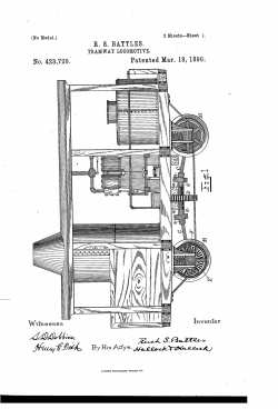
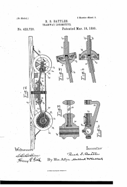
My invention is illustrated in the accompanying drawings,V in which- Figure'l is a side elevation of a tramwaylocomotive containing my invention. Fig-2 is a longitudinal central section through the truck and running-gear. Fig. 3 shows the lower half of one of the journal-boxes of the driving-shaft. Fig. 4 is a longitudinal vertical section through said journal-box. Figs. 5 and 6 are sectional views showing the construction of the universal joints in the driving-shaft.
The letters of reference indicate like parts in all the figures, as follows: A marks the platform of the locomotive; B, the wheels; B', the axles; C C, the end sections of the driving-shaft; C', the middle section of the driving-shaft; D, the driving-gear; E, the gears on the axles; F, the pinions on the driving shaft; c o', the universal joints in the driving shaft; G, the boxes in which the ends of the driving-shaft are journaled.4 Other letters of reference will be referred to in place in the description.
My invention is applicable to that class of tramway-locomotives in which there are two driven axles--one at each end of the locomotive. The axles are driven by a main driving-shaft, which has pinions which mesh with gears on the axles. The driving-shaft has to Witnesses the end sections. The outer ends of the end sections of the shaft are journaled in boxes G, which are hung on the axles B. The middle section of the shaft is journaled in boxes fixed on the cross-timbers o. a of the platform. The shaft C is always horizontal or parallel with the platform A, while the angle of' the shafts C to the shaft C varies according to the amount of Weight there is upon the platform, and this varies as the amount of coal in the coal-box and water in the watertank and boiler varies. This change of angularity of the shaft C is -permitted by the j box G being pivoted on the axles and the universal joint permitting the longitudinal movement of the shafts C in the joint. These universal joints are made up of the parts c on t-he shaft C, and the part c on the shaft C', which parts are of ordinary construction. In the part c there is a socket, lin which the rounded end c"2 of the shaft C sets. The part c of the joint is keyed by the key c5 to the shaft C', and on the part c is provided with a 'spline'o which enters a groove in the shaft C.
The object in V, having the shaft C extend beyond the part c and enter the socket at the end of the shaft C', as shown, is to prevent rattling. The boxes G have a shaftway g', with 'an offset g2 which receives the shaft C, and a collar or head on that shaft tits into the offset g2. These boxes also have an arm g, which extends back of the pinion F and embraces the shaft so as to give a bearing on both sides of the pinion.' These boxes also have a shaftway g3 at right angles to and in the same plane as the shaftway g. This last described shaftway receives the axle B.
What I claim as new is- .In a tramway-locomotive, the combination, with the middle section, of the shaft C', having sockets at its ends, and the end sections of the shaft C having balls c2 fitting in the said sockets of the universal-joint sections c, connected with the shafts C by a spline and groove, and the joint-sections c', connected with the shaft C by a key.
In testimony whereof I affix my signature in presence of two witnesses.
RUSI-I S'. BATTLES.
JNO. K. I-IALLooK, WM. P. HAYES.
IOO
Last edited:
